The Drill Down, Issue #5: What is a Production Facility?

Introduction
When an area offshore has been identified as potentially bearing large amounts of hydrocarbons (oil and gas), a well or series of wells are drilled to determine the economic viability of the hydrocarbon reservoir in the subsurface. If the reservoir is proven profitable, an Outer Continental Shelf (OCS) Facility intended for reservoir production (commonly known as a production facility) is eventually installed. This facility’s scope of operation would be to bring hydrocarbons to surface, process (separate the oil, gas and water from the produced mixture) and transfer oil and gas to shore. By regulation, there are two overarching categories of production facilities: Fixed OCS Facilities and Floating OCS Facilities.
What is a Fixed OCS Facility?
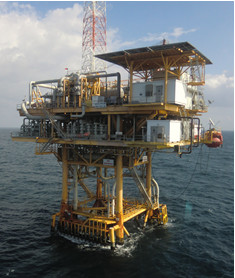 As defined in 33 CFR 140.10, a “fixed OCS facility means a bottom founded OCS facility permanently attached to the seabed or subsoil of the OCS including platforms, guyed towers, articulated gravity platforms, and other structures.” A fixed OCS facility, more commonly referred to as a fixed platform, consists of a bottom bearing rigid structure extending to the seafloor. Often the portion of a fixed OCS facility visible above the surface of the water is a small fraction of the overall structure. A topside “platform” is installed on top of the structure (image right).
Most common operations conducted from fixed platforms consist of production, processing as well as drilling capability on some platforms. Additionally many platforms serve as “boost” stations which provide the needed pressure to pump hydrocarbons through subsea pipelines to shore for further refinement. The U.S. OCS hosts more than 2,000 fixed facilities, most of which are in the Gulf of Mexico. The deepest Fixed OCS Facility in the U.S. sits in 1,754 feet of water in the Gulf of Mexico.
What is a Floating OCS Facility?
As defined in 33 CFR 140.10, a “floating OCS facility means a buoyant OCS facility securely and substantially moored so that it cannot be moved without special effort.” The Marine Safety Manual elaborates that a floating facility “maintains a fixed location over the OCS, through moorings, and may be attached to the subsoil or seabed by flow-lines, umbilicals or similar connectors. This term includes, but is not limited to floating production systems (FPS), floating production storage and offloading systems (FPSO),…Spars and other similar types of installations or devices.”
While some Floating OCS Facilities are capable of drilling new wells, the primary purpose for all of these facilities is the production of hydrocarbons, often from multiple wells at one time. In contrast to fixed OCS facilities, Floating OCS Facilities are capable of being located in much deeper water. Due to the physical (and financial) limitations of installing Fixed OCS Facilities in deeper water, Floating OCS Facilities are designed to float and are anchored to the seafloor. Thus beyond this water depth, only floating facilities can be found.
Floating OCS Facilities on the U.S. OCS
A commonly used term on the U.S. OCS for many Floating OCS Facilities is “Floating Offshore Installation” (FOI), which consist of multiple designs: Spars, Tension Leg Platforms (TLPs), and Semi-Submersibles.
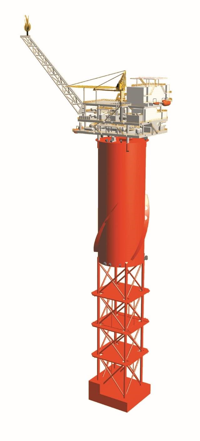 Spars consist of a cylindrical hull hundreds of feet in depth, typically 550-600 ft. draft (image right). This design maintains stability with heavy ballast at the bottom of the hull, typically a tank filled with a dense metal slurry. The hull is held in position by an anchor mooring spread spanning several miles. The production risers, the conduits through which hydrocarbons from the well(s) flow, ordinarily come to the topside of the facility through the center of the hull. The most common Spar type in the U.S. is the Truss Spar (image right). Spars are the most common FOI on the U.S. Outer Continental Shelf at 19 facilities.
Spars are a common selection for extremely deep water. The deepest FOI location on the U.S. OCS is occupied by a Spar in 8,000 ft. water depth. This facility is home to one of the deepest subsea well completions at 9,596 ft. water depth. While advantageous for stability and deep water capability, Spars are limited in deck space and well bays, thus limiting ability for expansion in the case of new discoveries nearby.
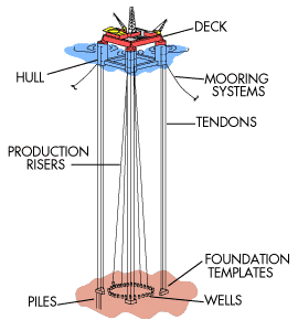 Tension Leg Platforms (TLPs) are designed to remain on location by a series of tendons that are substantially moored to the seafloor. The tendons are attached at the bottom to anchor piles set in the seafloor. When installed on location, the hull is ballasted down below operating draft, and the tendons are latched into connectors on the lower hull structure. The TLP (image left, source: Shell) is then de-ballasted to design operating draft, drawing an extreme amount of tension on the tendons (typically well over 1,000,000 lbs. per tendon). Production risers come to surface centrally in the well bay or up the side of the hull. The tension on the tendons significantly reduces heave, which allows for wellheads to be located at the facility vs. subsea. This makes well access and maintenance more convenient and less costly. TLPs are limited in the depth of water they can be anchored. The deepest TLP on the U.S. OCS sits at 4,674 ft., and most are located in no less than 3,000 ft. water depth. Conventional TLPs have a four-column structure design, allowing a larger area for more wells, equipment, and expansion. The tendon mooring design adds complexity to TLP stability, requiring constant and accurate monitoring of tendon tension, as well as varying deck loads on the facility. There are 17 TLPs on the U.S. OCS.
Semi-submersibles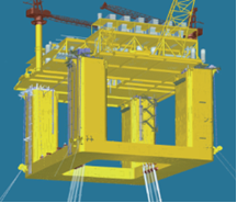 are similar to TLP structures; however, these FOIs are large, column-stabilized structures that are conventionally moored to the seafloor by a mooring array similar to that of a Spar. Semi-submersibles (image right, source: Aker Solutions) are typically installed in large-prospect areas, where many well bays and more equipment will be needed to accommodate higher production rates. Stability and ballast must be monitored carefully due to the potential for large changes in deck loads. These facilities can be much larger than any other FOI design. One of the largest on the U.S. OCS is moored in 6,040 ft. of water, contains close to 4 acres of deck area, and is capable of producing up to 250,000 barrels of oil per day. The U.S. OCS hosts 12 Semi-submersible FOIs.
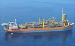 Floating, Production, Storage & Offloading Units (FPSOs)
A new development in recent years on the U.S. OCS is the introduction of FPSOs (image left). These production facilities are commonly a ship-shaped design and are attached to the seafloor by a substantially moored production buoy. This buoy contains riser flow lines from subsea wellheads. In a typical FPSO design, this buoy is attached to the FPSO near the bow of the vessel. Once attached, the FPSO no longer uses propulsion and uses the production buoy as a mooring, and the FPSO can detach from the buoy at any time. FPSOs are typically employed for geographically isolated locations which may not have pipeline infrastructure and the hydrocarbon prospects are marginally economic. Installing an FOI is a multi-billion dollar investment, whereas use of an FPSO can be less expensive. Instead of relying on pipeline infrastructure to pump produced hydrocarbons to shore, FPSOs transfer product to shuttle tank ships which bring product to shore. There are currently 2 ship-shaped FPSOs operating on the U.S. OCS.
Conclusion
While there are thousands of Fixed OCS Facilities versus the relatively smaller number of Floating OCS Facilities, the difference in hydrocarbon production quantities between the two categories is rather significant. While less than 3% of existing facilities are Floating OCS Facilities, they contribute roughly 82% and 54% of U.S. offshore oil and gas production, respectively. The image to the right (Source: MODEC) portrays the Fixed and Floating OCS Facilities on the U.S. OCS.