Determining a Vessel's Load Line Length
Overview
One of the factors which determines if a vessel might be required to have a load line is its length, as calculated by load line regulations. The length determination is the same for both international ICLL and domestic U.S. load line purposes.
A vessel's load line length is measured on a particular waterline, determined by its molded hull depth (the vertical dimension from the top of the keel to the underside of the freeboard deck at the vessel's side).
Specifically, it is the waterline located at 85 percent of the least molded depth of the hull, measured up from the keel. For vessels that have a flat freeboard deck (no sheer) that is parallel to a flat keel, this is a fairly straightforward determination. However, for vessels that have discontinuous or stepped freeboard decks, or a raked keel, and/or deck sheer, determining the least molded depth is a little more involved.
The methods for determining a vessel's load line length are presented below, followed by additional considerations and discussions of the relevant terms.
Determining Load Line Length -- Flat keel
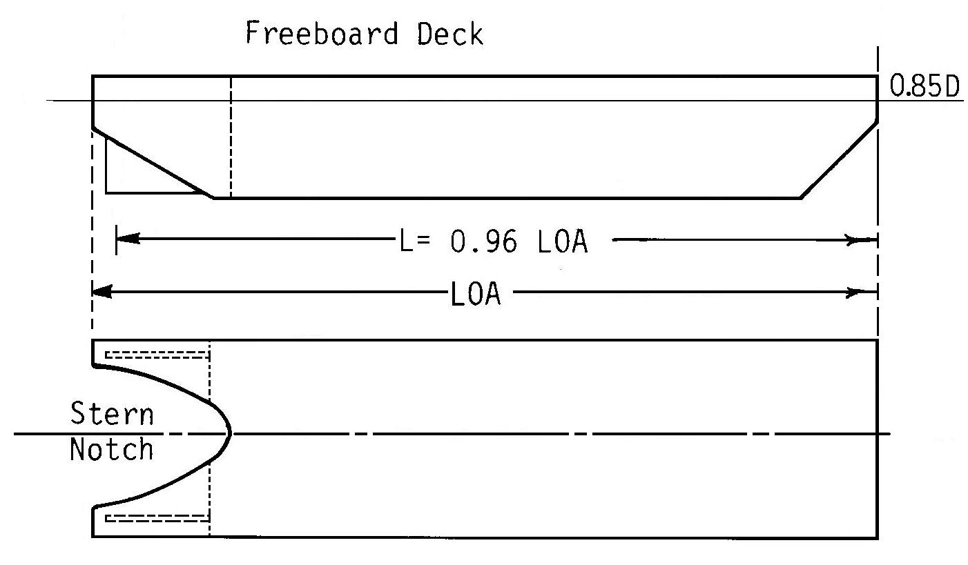
The load line length is measured on waterline "d1" at 85 percent (0.85D) of the least molded depth "D." The load line length is either:
- 96 percent of the total waterline length, or
- the waterline length from the FP (forward side of the stem) to the axis of the rudder stock, whichever is longer.
In the figure above, the freeboard deck is parallel to the keel (i.e., no sheer), so the molded depth is also the least molded depth at every point along the hull. If the vessel's least molded hull depth "D" is 30 feet, then the length is measured on the "d1" waterline 25.5 feet up from the top of the keel. The load line length is either 96 percent of that waterline length, or the waterline length from the FP to the axis of the rudder stock, whichever is longer.
Determining Load Line Length -- Discontinuous Freeboard Deck
Where the freeboard deck is stepped and the raised part of the deck extends over the point at which the molded depth is to be determined, the molded depth "D" is to be measured to a reference line extending from the lower part of the freeboard deck and parallel to the raised part.
The load line length is measured on the 0.85D waterline as per above.
Determining Load Line Length -- Stepped Freeboard Deck
Where the freeboard deck is interrupted by a step which extends across the full width of the deck, and the stepped span is more than 3.28 feet (1 meter) in length, the least molded depth is to be measured at the lowest point of a reference line extending from the lower level of the freeboard step and parallel with the raised part.
The load line length is measured on the 0.85D waterline as per above.
If the step does not extend across the full width of the deck, then the step is treated as a recess, and the least molded depth is measured at the lowest point of the freeboard deck
(the recess is taken into consideration later as a freeboard correction).
Determining Load Line Length -- Raked keel, deck sheer
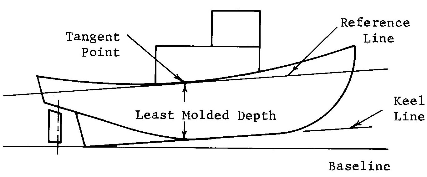
For vessels with a raked keel and/or deck sheer (such as some tugs or fishing vessels), the molded depth changes from point to point along the hull, depending on the rake of the keel and the sheer curve of the freeboard deck. It should also be noted that the top of a raked keel does not coincide with the baseline (the molded depth is always measured from the keel).
Step 1: To determine the least molded depth, draw a reference line parallel to the keel line (skeg included) which is tangent to the lowest point of the freeboard deck. The least molded depth "D" is the vertical dimension from the keel to the tangent point. Because of the sheer curve, the tangent point might not occur at midships.
Step 2: Draw a horizontal waterline "d1" at 85 percent of the least molded depth (0.85D), measured up from the keel opposite the tangent point. The intersection of this waterline with the forward side of the stem marks the forward perpendicular (FP). The load line length is either 96 percent of the waterline length or the length from the FP to the rudder stock axis, whichever is longer.
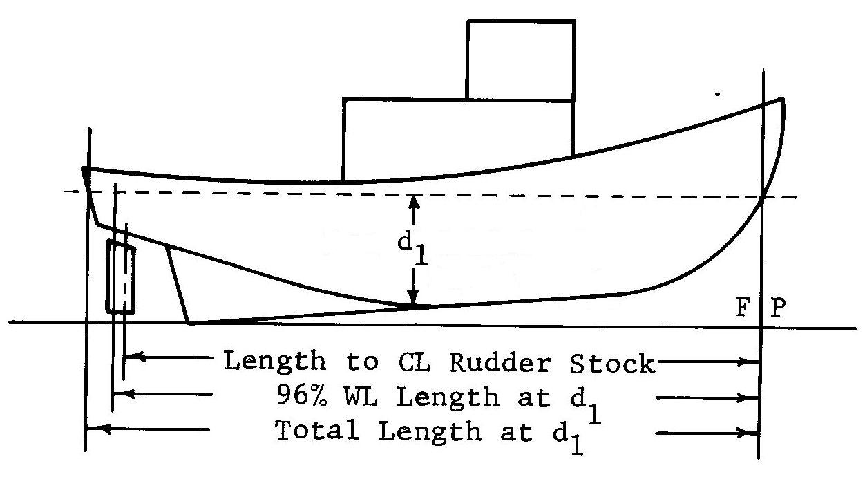
In the figure above, the molded depth is not constant along the hull. If the vessel's least molded hull depth "D" at the tangent point is 10 feet, then the length is measured on the "d1" waterline 8.5 feet up from the top of the keel (not from the baseline). The load line length is either 96 percent of this waterline length, or the waterline length from the FP to the axis of the rudder stock, whichever is longer.
Determining Load Line Length -- Additional considerations
The methods illustrated above will cover a great majority of vessel designs. However, there are still some designs for which additional considerations apply:
- "Freeboard deck:" The freeboard deck is normally the uppermost complete deck (bow to stern) exposed to weather, although portions of it might be enclosed by a focs'l, superstructure, or quarterdeck. For many vessels, it is also the Main Deck. In certain designs, a lower internal deck could be designated as the freeboard deck if it meets special requirements. The freeboard assignment is measured down from the freeboard deck edge.
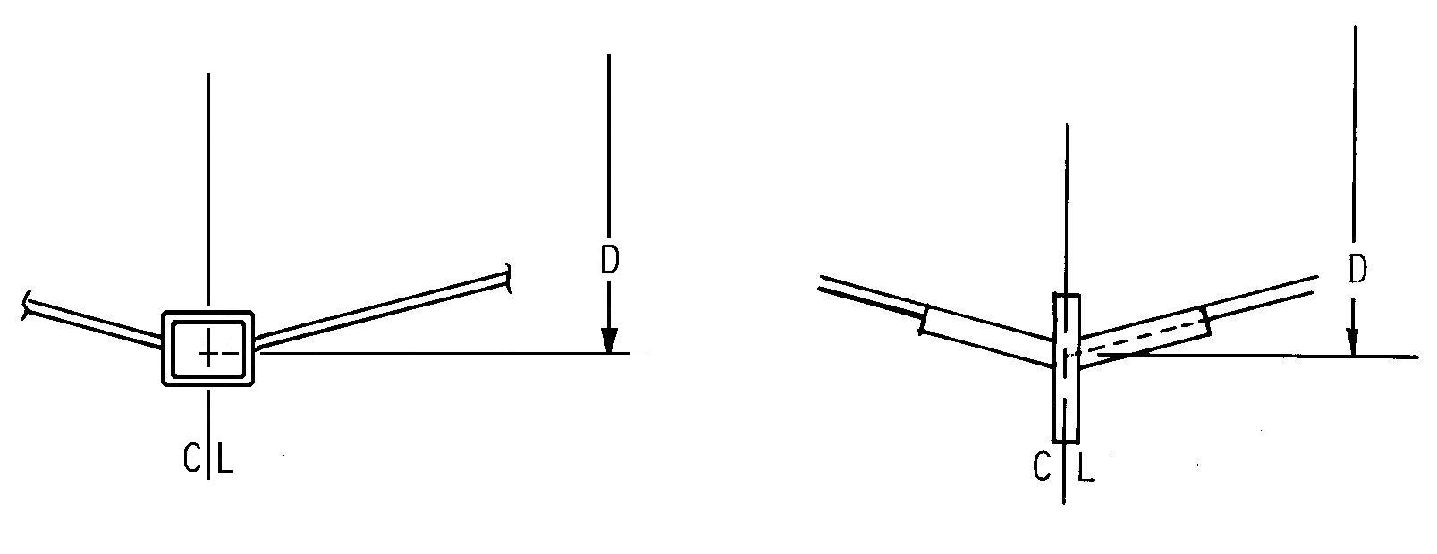
- "Top of keel:" The molded depth is measured from the top of the keel. For wood or composite vessels, the depth is measured from the lower edge of the keel rabbet. For vessels with a flat steel keel plate, the molded depth is measured from the upper surface of the plate. For other steel keel designs, the "top" point is located where the extended line of the hull plating intersects the centerline:
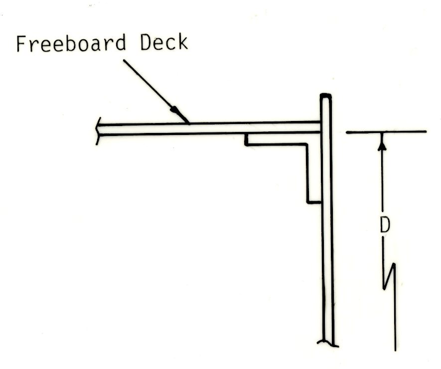
- "Underside of freeboard deck:" The molded depth is measured up to the underside of the freeboard deck plating or planking, at the vessel's side (not centerline):
- Vessels without a rudder stock: For barges and similar hulls, the load line length is simply 96 percent of the total waterline length on the 0.85D waterline.
- Vessels with vertical axis or azimuthing "Z-drives:" The axis of the propulsion system is not substituted for the axis of a rudder stock. For such vessels, the load line length is simply 96 percent of the total waterline length on the 0.85D waterline.
- Vessels with stern notches: For barges with stern notches or cutouts, the load line length is still 96 percent of the 0.85D waterline length, unless the notch is so large that there is minimum buoyancy below the waterline. In such cases, it may be appropriate to treat the notch "wings" as appendages.
- Vessels with concave stems above the waterline: Some vessel bows have substantial concave stems above the 0.85D waterline. In such cases, the forward perpendicular (FP) is vertically tangent to the aftermost curvature point of the stem (wherever that occurs above the waterline):